
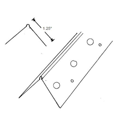
EB Metal Cornerbead provides the strongest corner protection in the market from it’s .015 thickness. It’s hot dipped galvinized protection provides superior corrosion protection and complies with ASTM A653. The flanges are punched and knurled for ease of joint compound adhesion.
Product Data and Ordering Information
Material: .015 thickness, minimum G40 galvinized
Dimensions: 1-1/4″ X 1-1/4″ legs
| Length | Pcs/Ctn | Feet/Ctn | Ctn/Pallet |
| 8′ | 63 | 504 | 42 |
| 9′ | 56 | 504 | 48 |
| 10′ | 50 | 500 | 48 |
| 12′ | 42 | 504 | 48 |
ASTM Codes and Standards
All EB Metal Cornerbeads meet or exceed the following standards:
* ASTM C 1047 Standard Specification for Accessories for Gypsum Wallboard
* ASTM A 653 Standard for Hot Dipped Galvanized Steel
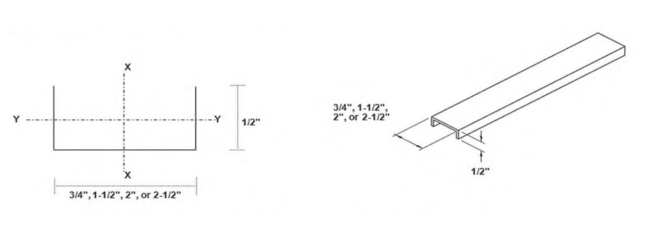
U-Channel Section |
||||||||||||
| Member | Design Thickness (in) | Yield strength, Fy (ksi) | Gross Properties | Effective Properties | ||||||||
| Area | Weight | Ix | Rx | Iy | Ry | Ix | Sx | Ma | Va | |||
| (in2) | (lb/ft) | (in4) | (in) | (in4) | (in) | (in4) | (in3) | (in-k) | (lb) | |||
| 075U050-54 | 0.0566 | 33 | 0.087 | 0.296 | 0.007 | 0.289 | 0.002 | 0.156 | 0.007 | 0.019 | 0.459 | 315 |
| 150U050-54 | 0.0566 | 33 | 0.130 | 0.441 | 0.039 | 0.549 | 0.003 | 0.146 | 0.039 | 0.052 | 1.230 | 840 |
| 200U050-54 | 0.0566 | 33 | 0.158 | 0.537 | 0.080 | 0.711 | 0.003 | 0.137 | 0.080 | 0.080 | 1.883 | 1190 |
| 250U050-54 | 0.0566 | 33 | 0.186 | 0.633 | 0.140 | 0.868 | 0.003 | 0.130 | 0.140 | 0.112 | 2.648 | 1540 |
1. Calculated properties are based upon AISI S100-07, North American Specification for the Design of Cold-Formed Steel Structural Members.
2. Minimum base steel thickness is 95% of design thickness.
3. Effective properties are based on Fy=33ksi.
Product Benefits
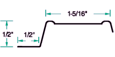
EB Metals RC-1 Resilient Sound Channels (Furring Channel) are fabricated from galvanized steel and designed to decrease sound transmission through wall partitions and ceilings/floors.
Additional benefits include:
• RC-1 Standard Duty has a minimum design thickness of .018”
• Deeply knurled for positive screw placement
• Works great to prevent ridging and cracking in ceilings
 Drawing not to scale
Certification
EB Metals RC-1 Resilient Sound Channels meet or exceed ASTM C 645 Standard Specification for Nonstructural Steel Framing Members.
Spacing Guidelines
Spacing of RC-1 resilient sound channel (furring channel) should not exceed 24” o.c. (16” o.c. if span is 24” o.c.).
Storage
Avoid bending or other damage and store in a dry place protected from moisture.
Installation Recommendations
EB Metals recommends installation in accordance with applicable ASTM standards and using prevalent industry standards. Reference materials include ASTM C 754, Gypsum Association GA-216, Gypsum Association GA-600
General Notes
1. Physical properties and load tables have been calculated in conformance with the 2001 NASPEC for the Design of Cold‐Formed Steel Structural Members, including the 2004 Supplement, and the IBC 2006, unless noted otherwise.
2. Drywall framing members have a protective coating conforming to ASTM spec A 653/A 653M, G‐40 min, or equivalent corrosion resistance.
3. Reference ASTM specification A 1003/A 1003M table 1 for the universe of allowable coatings for light gauge steel framing.
4. Drywall framing members are marked with product information per the requirements of ASTM C 645 section 14.
5. All delivered material must be kept dry, preferably by being stored inside a building under a roof. If it is necessary to store material outside, it must be stacked off the ground, properly supported on a level platform, and fully protected from the weather. Reference ASTM C 754 section 8 and ASTM C 1007 section 4.
6. Drywall framing [nonstructural 25 gauge, 22 gauge and 20 gauge] is not permitted in load bearing
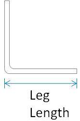
| Leg Length | Thickness (mils) | Gauge | Length | |||||||||||||||||||||||||||||||||||||||
| 7/8″ x 1‐3/8″ | 18 | 25 | 10′ or custom lengths | |||||||||||||||||||||||||||||||||||||||
| 27 | 22 | |||||||||||||||||||||||||||||||||||||||||
| 30 | 20 | |||||||||||||||||||||||||||||||||||||||||
| 1‐1/2″ x 1‐1/2″ | 18 | 25 | ||||||||||||||||||||||||||||||||||||||||
| 27 | 22 | |||||||||||||||||||||||||||||||||||||||||
| 30 | 20 | |||||||||||||||||||||||||||||||||||||||||
| 43 | 18 | |||||||||||||||||||||||||||||||||||||||||
| 54 | 16 | |||||||||||||||||||||||||||||||||||||||||
| 2″ x 2″ | 18 | 25 | ||||||||||||||||||||||||||||||||||||||||
| 27 | 22 | |||||||||||||||||||||||||||||||||||||||||
| 30 | 20 | |||||||||||||||||||||||||||||||||||||||||
| 43 | 18 | |||||||||||||||||||||||||||||||||||||||||
| 54 | 16 | |||||||||||||||||||||||||||||||||||||||||
| 68 | 14 | |||||||||||||||||||||||||||||||||||||||||
| 3″ x 3″ | 18 | 25 | ||||||||||||||||||||||||||||||||||||||||
| 27 | 22 | |||||||||||||||||||||||||||||||||||||||||
| 30 | 20 | |||||||||||||||||||||||||||||||||||||||||
| 43 | 18 | |||||||||||||||||||||||||||||||||||||||||
| 54 | 16 | |||||||||||||||||||||||||||||||||||||||||
| 68 | 14 | |||||||||||||||||||||||||||||||||||||||||

| Leg Length | Thickness (mils) | Gauge | Length |
| 1″ | 18, 27, 30, 33, 43, 54, 68, 97 | 25, 22, 20D, 20S, 18, 16, 14, 12 | 10′ or custom lengths |
| 1-1/2″ | |||
| 2″ | |||
| 3″ | |||
| 4″ | |||
| 5″ | |||
| 6″ | |||
| 7″ | |||
| 8″ | |||
| 9″ | |||
| 10″ | |||
| 11″ | |||
| 12″ |
General Notes
1. Physical properties and load tables have been calculated in conformance with the 2001 NASPEC for the Design of Cold-Formed Steel Structural Members, including the 2004 Supplement, and the IBC 2006, unless noted otherwise.
2. Drywall framing members have a protective coating conforming to ASTMspec A 653/A 653M, G-40min, or equivalent corrosion resistance.
3. Reference ASTMspecificationA 1003/A 1003M table 1 for the universe of allowable coatings for light gauge steel framing.
4. Drywall framing members are marked with product information per the requirements of ASTMC 645 section 14.
5. All delivered material must be kept dry, preferably by being stored inside a building under a roof. If it is necessary to store material outside, it must be stacked off the ground, properly supported on a level platform, and fully protected from the weather. Reference ASTM C 754 section 8 and ASTMC 1007 section 4.
6. Drywall framing [nonstructural 25 gauge, 22 gauge and 20 gauge] is not permitted in load bearing (i.e. axial load greater than 200 lbs.) or exterior applications (i.e. transverse load greater than 10 PSF). Reference ASTMC 645 section 3.2.2.
3″1825
| Size | Thickness (mils) | Gauge | Length | |||||||||||||||||||
| 1″ | 18 | 25 | 8′ 6″, 10′, 12′ or custom lengths | |||||||||||||||||||
| 27 | 22 | |||||||||||||||||||||
| 30 | 20 | |||||||||||||||||||||
| 43 | 18 | |||||||||||||||||||||
| 1-1/2″ | 18 | 25 | ||||||||||||||||||||
| 27 | 22 | |||||||||||||||||||||
| 30 | 20 | |||||||||||||||||||||
| 43 | 18 | |||||||||||||||||||||
| 2″ | 18 | 25 | ||||||||||||||||||||
| 27 | 22 | |||||||||||||||||||||
| 30 | 20 | |||||||||||||||||||||
| 43 | 18 | |||||||||||||||||||||
| 2-1/2″ | 18 | 25 | ||||||||||||||||||||
| 27 | 22 | |||||||||||||||||||||
| 30 | 20 | |||||||||||||||||||||
| 43 | 18 | |||||||||||||||||||||
| 27 | 22 | |||||||||||||||||||||
| 30 | 20 | |||||||||||||||||||||
| 43 | 18 | |||||||||||||||||||||
General Notes
1. Physical properties and load tables have been calculated in conformance with the 2001 NASPEC for the Design of Cold-Formed Steel Structural Members, including the 2004 Supplement, and the IBC 2006, unless noted otherwise.
2. Drywall framing members have a protective coating conforming to ASTMspec A 653/A 653M, G-40min, or equivalent corrosion resistance.
3. Reference ASTMspecificationA 1003/A 1003M table 1 for the universe of allowable coatings for light gauge steel framing.
4. Drywall framing members are marked with product information per the requirements of ASTMC 645 section 14.
5. All delivered material must be kept dry, preferably by being stored inside a building under a roof. If it is necessary to store material outside, it must be stacked off the ground, properly supported on a level platform, and fully protected from the weather. Reference ASTM C 754 section 8 and ASTMC 1007 section 4.
6. Drywall framing [nonstructural 25 gauge, 22 gauge and 20 gauge] is not permitted in load bearing (i.e. axial load greater than 200 lbs.) or exterior applications (i.e. transverse load greater than 10 PSF). Reference ASTMC 645 section 3.2.2.
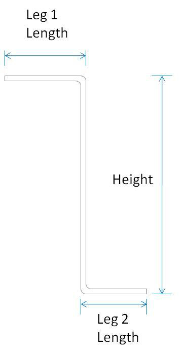
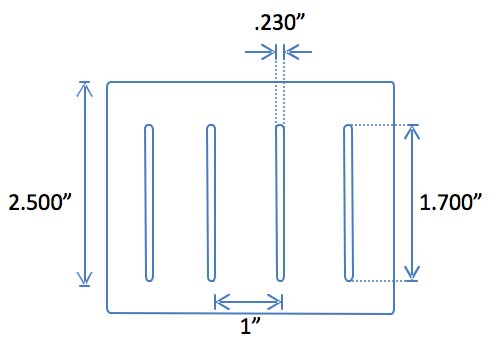
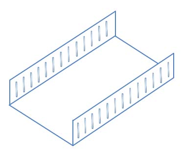
Slotted Track
Slotted Track is used in conditions that may contain vertical movement within the framing structure.
EB Metal slotted track is available in web. Slotted Track is available in 25 gauge thru 16 gauge.
| Thickness (in) | |||
| Mills | Gauge | Design | Minimum * |
| 18 | 25 | 0.0188 | 0.0179 |
| 33 | 20 | 0.0346 | 0.0329 |
| 43 | 18 | 0.0451 | 0.0428 |
| 54 | 16 | 0.0566 | 0.0538 |
| 68 | 14 | 0.0695 | 0.0660 |
* Minimum Thickness represents 95% of the design thickness and is the minimum acceptable thickness delivered to the job site based on Section A3.4 of the 1996 AISI Specification.
Dimensions
Web Width 2-1/2”, 3-5/8”, 4”, 6”, 8”
Yield Strength 33 ksi for 25ga, 20ga, & 18ga 50 ksi for 16ga & 14ga
Coating G40 for 25ga DW G60 for 20ga STR – 14ga.
Leg Length 2-1/2”
Slot Strength 1-7/10”
General Notes
1. Physical properties have been calculated in conformance with the 2001 NASPEC for the Design of Cold-Formed Steel Structural Members,
including the 2004 Supplement, and the IBC 2006, unless noted otherwise.
2. Drywall framing members have a protective coating conforming to ASTM spec A 653/A 653M, G-40 min, or equivalent corrosion resistance.
3. All structural framing members have a protective coating conforming to ASTM C 955.
4. Reference ASTM specification A 1003/A 1003 M table 1 for the universe of allowable coatings for light gauge steel framing.
5. All delivered material must be kept dry, preferably by being stored inside a building under a roof. If it is necessary to store material outside, it must be stacked off the ground, properly supported on a level platform, and fully protected from the weather. Reference ASTM C 754 section 8 and ASTM C 1007 section 4.
6. Drywall framing [nonstructural 25 gauge, 22 gauge and 20 gauge] is not permitted in load bearing (i.e. axial load greater than 200 lbs.) or exterior applications (i.e. transverse load greater than 10 PSF). Reference ASTM C 645 section 3.2.2.
7. Track is produced in standard lengths of 10 feet unless a custom track length is indicated. Track is manufactured with unpunched webs.