
Code Approval
The data provided by EB Metal US is based upon the North American Specification for the Design of Cold-Formed Steel Structural Members, S100-16 (2020) w/ Supplement 2-20 using U.S. provisions and meets the requirements of the IBC 2015 Building Code, as well as the 2011 California Building Code. While building codes vary by jurisdiction, this guide follows the most recent international standards published by the International Code Council, the most widely recognized building code authority in North America.
Material Specifications
Products manufactured by EB Metal US are formed from steel with a minimum yield stress of 33 or 50 kips per square inch (ksi). Unless noted otherwise, all products are engineered to meet the North American Specification for the Design of Cold-Formed Steel Structural Members, S100-16 (2020) w/ Supplement 2-20 using U.S. provisions and other AISI standards referenced in section 2210 of the 2015 International Building Code (IBC-2015). The structural properties have been computed based upon allowable stress design (ASD) which includes distortional buckling considerations for all stud sections. For fastener tables, the screw sizes and head diameters do not refer to specific fasteners which may or may not be available from EB Metal US. Shear and tension data for screws was developed using published manufacturer data and evaluation reports available at the time of publications.
Technical Assistance
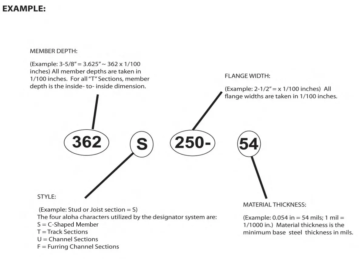
EB METAL US supports the industry standard nomenclature published in the American Iron and Steel Institute’s (AISI) General Provisions, S240. The AISI S240 states in Section A5.3 that ”structural members and non-structural members shall use a four-part product designator that identifies the size (both web depth and flange width), style and thickness.” An example of this designator is shown below:
Thickness – Steel Components |
||||
| Designation Thickness (Mils) | Thickness Minimum (in) 1 | Thickness Design (in) | Inside Radii Design Corner 2 (in) | Reference Gauge No. |
| 18 | 0.0179 | 0.0188 | 0.0844 | 25 |
| 27 | 0.0269 | 0.0283 | 0.0796 | 22 |
| 30 | 0.0296 | 0.0312 | 0.0782 | 20-Dw |
| 33 | 0.0329 | 0.0346 | 0.0765 | 20-Str |
| 43 | 0.0428 | 0.0451 | 0.0712 | 18 |
| 54 | 0.0538 | 0.0566 | 0.0849 | 16 |
| 68 | 0.0677 | 0.0713 | 0.1070 | 14 |
| 97 | 0.0966 | 0.1017 | 0.1526 | 12 |
| 118 | 0.1180 | 0.1242 | 0.1863 | 10 |
Stiffening Lip Length |
|||||
| Member | FlangeWidth | DesignLipLengthStiffening(in) | |||
| S125 | 11/4” | 0.188 | |||
| S137 | 13/8” | 0.375 | |||
| S162 | 15/8” | 0.500 | |||
| S200 | 2” | 0.625 | |||
| S250 | 21/2” | 0.625 | |||
| S300 | 3” | 0.625 | |||
| S350 | 31/2” | 1.000 | |||
General Notes for all Tables
- Where AISI S100 is referenced, it is the North American Specification for the Design of Cold-Formed Steel Structural Members, S100-16 (2020) w/ Supplement 2-20 using U.S. provisions.
- The strength increase from cold work of forming has been incorporated for the effective properties per AISI S100 Section A3.3
- The effective moment of inertia for deflection is calculated at a stress which results in a section modulus such that the stress times the section modulus at that stress is equal to the allowable moment. AISI S100 Appendix 1, Procedure I for serviceability determination has been used. Increases in the effective moment of inertia may be possible at lower stress levels. Any modified values must be calculated by a qualified engineer.
- Various members may be manufactured with yield strengths of 33 or 50 kips per square inch (ksi). The yield strength used for calculations is indicated in the tables.
- For members available in both 33 and 50 ksi, the specifier must clearly indicate which yield strength is required. For example: 3625162-54 (50ksi).
- When provided, factory punchouts will be located along the center line of the webs of the stud members and will have a minimum center-to-center spacing of 24″. Punchouts for members greater than 2 ½” deep are a maximum of 1 ½” wide x 4 ½” long. Members with depths 2 ½” and smaller are maximum ¾” wide x 4 ½” long. Any configuration or combination of holes that fit within the width and length limitations mentioned above are permitted.
- Allowable flexural strength values in the table (Ma) are based upon local buckling. Allowable distortional buckling strength values in the table (Mad) are based on a k-phi of 0. Higher values may be obtained when sheathing is applied to the walls
Warranty & Limitations
All products presented herein are warranted to the buyer to be free from defects in material and workmanship.
The foregoing warranty is non-assignable and in lieu of and excludes all other warranties not expressly set forth herein, whether express or implied by operation of law or otherwise, including but not limited to any implied warranties of merchantability or fitness for a particular purpose. All details and specifications presented herein are intended as a general guide for the use of EB Metal US framing systems. These products should not be used without evaluation by a qualified engineer or architect to determine their suitability for a specific use. EB Metal US assumes no responsibility for failure resulting from use of its details or specifications, or for failure resulting from improper application or installation of these products.